Slip Ring Motor Starter Wiring Diagram
What is motor starter? types of motor starters Electrical schematic – motor starting system – slip ring motor starting Construction of three phase induction motor
What is Motor Starter? Types of Motor Starters - Electrical Technology
3 phase slip ring induction motors: 220 v Slip ring electric motor wound rotor motor wiring diagram, png Slip ring starter phase rotor power three control diagram diagrams
Slip rings three motor induction rotor wound phase ring brush circuit concepts assembly rotating machine electrical fig engineering stationary connecting
Slip starter magna resistance induction liquidBack to basics: may/june 2021 – slip rings – wiring harness news Guide to the power circuit and control circuit of the wound rotor acElectrical standards: slip ring induction motors starting; slip ring.
Motor synchronous starting methods slip ring induction method motors resistance rotor principle working speed damper self electrical torque squirrel cageWhy the rotor of slip ring induction motor always star connected Starting of an induction motorMedium voltage soft starter for heavy-duty motor control.

Induction poles stator
Rotor starters electrical resistors electricaltechnologyMotor induction starting circuit slip ring starter method methods connected supply diagram phase rotor connection start resistance current motors circuitglobe Difference between slip ring & squirrel cage induction motor withMagna start – new generation slip-ring motor starter.
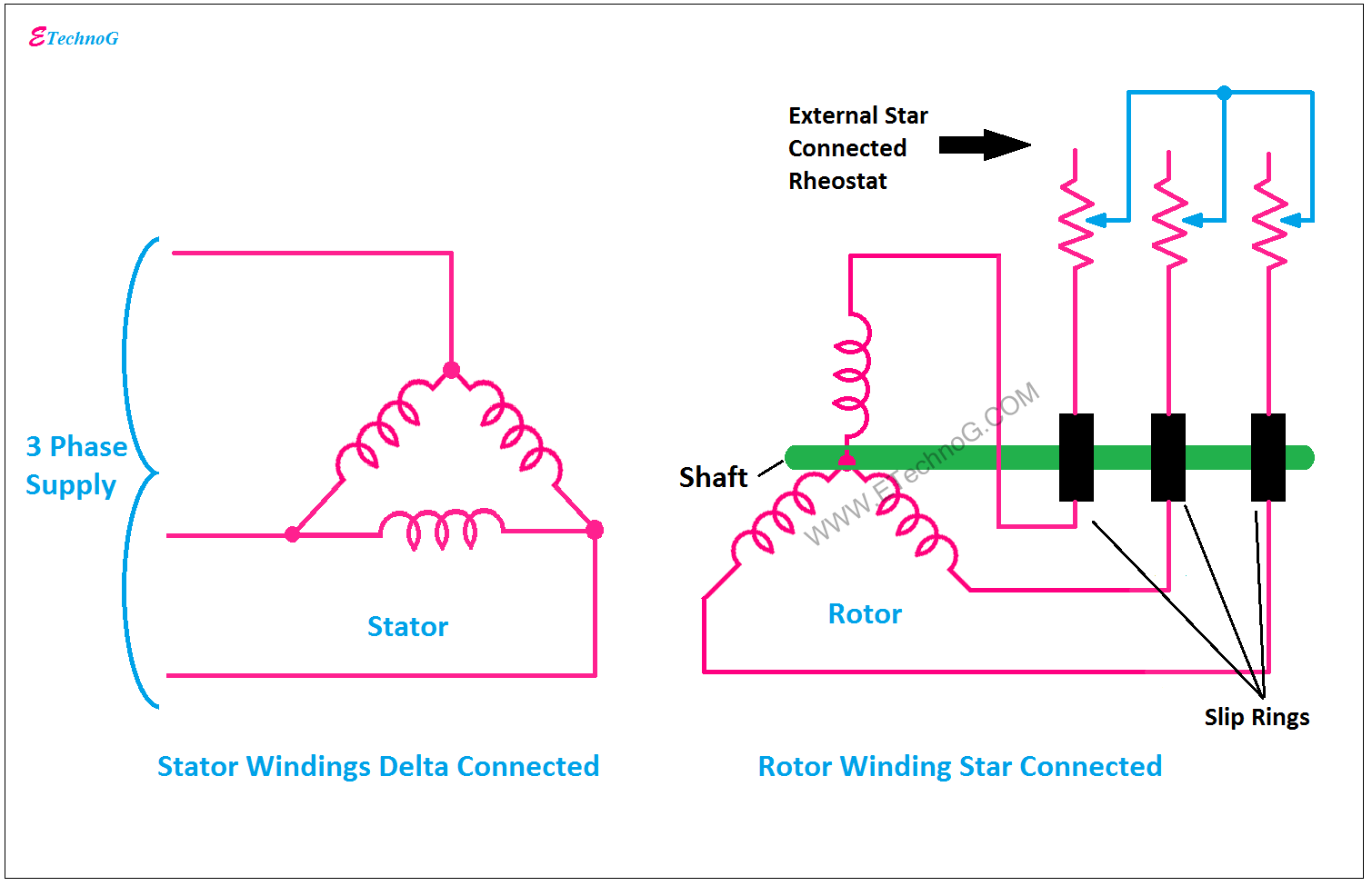
Slip motor induction ring star connected rotor delta diagram connection why which very will always explained reasons problem simple thereSelf start 3-φ induction motor slip-ring wound rotor starter Kbreee: methods of starting synchronous motorMotor ring slip diagram rotor wound electric wiring commutator brush favpng.

Phase induction motor three construction slip ring starter diagram rotor cage squirrel winding wound motors main resistance engineering circuit connection
Motors induction menzel ic411Motor rotor circuit wound power electrical diagram control schematic induction bank wiring automatic hoist ac resistors guide used step electronics Concepts of slip rings and brush assembly in three phase inductionSlip starting ring motor diagram induction starter motors circuit control.
Schematic expert slipring cannot startedSlip rings .

3 phase slip ring induction motors: 220 V - 13,800 V
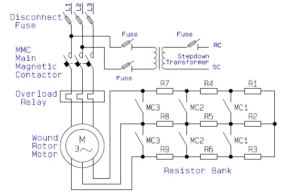
Guide to the Power Circuit and Control Circuit of the Wound Rotor AC

Medium voltage soft starter for heavy-duty motor control | EEP
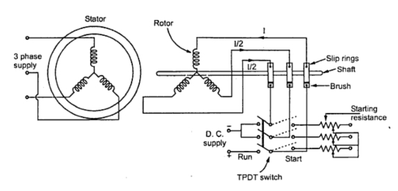
KBREEE: Methods of Starting Synchronous Motor

Self Start 3-Φ Induction Motor Slip-Ring Wound Rotor Starter

Starting of an Induction Motor - Starting Methods - Circuit Globe

What is Motor Starter? Types of Motor Starters - Electrical Technology

Back to Basics: May/June 2021 – Slip Rings – Wiring Harness News

Construction of Three Phase Induction Motor | Electrical4U